This repository holds the firmware code, and a basic schematic for an AX.25 Terminal Node Controller (TNC) suitable for amateur radio 1200-baud packet radio communication.
The repository may be cloned via
git clone https://gitlab.com/davidplatt/opentnc
Unless otherwise noted, code in this repository was written by David Platt AE6EO, and is released under the terms of the GNU General Public License, Version 3.0. The sample hardware schematic is released under the Creative Common CC BY-SA license.
Commercial use of this design is permitted, as long as you comply with the above licenses. If you decide to build and sell TNCs based on this design, it would be gracious of you to send me one as a thank-you (not required, but nice).
12/19/2023 - Version 2.0 of the firmware is released. Adds FX.25 forward error correction, DAMASK packet scheduling mode for KISS- connected nodes, and internal improvements. See RELEASE-NOTES.md in the git archive for details.
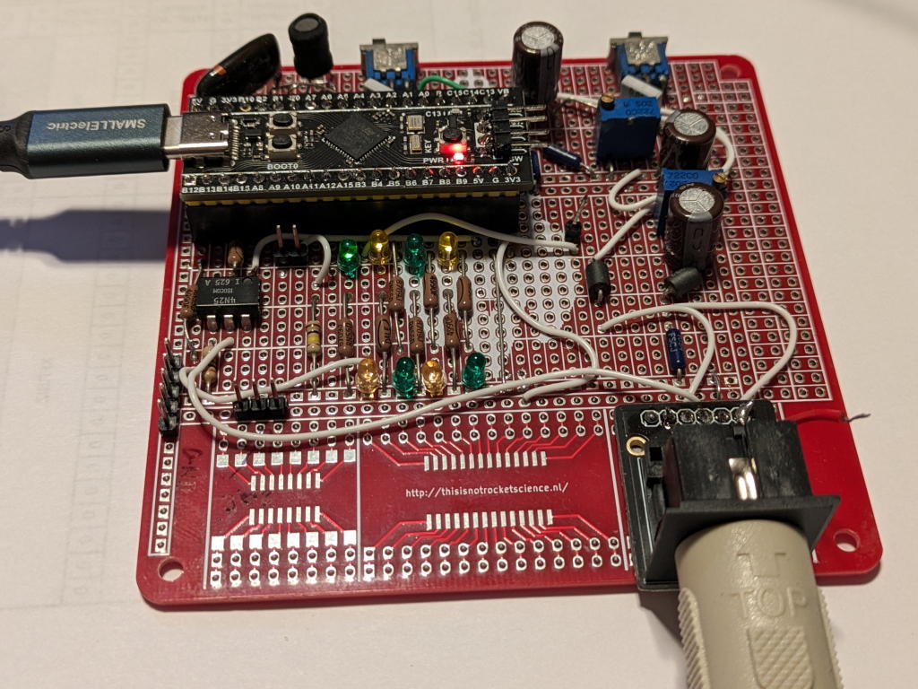
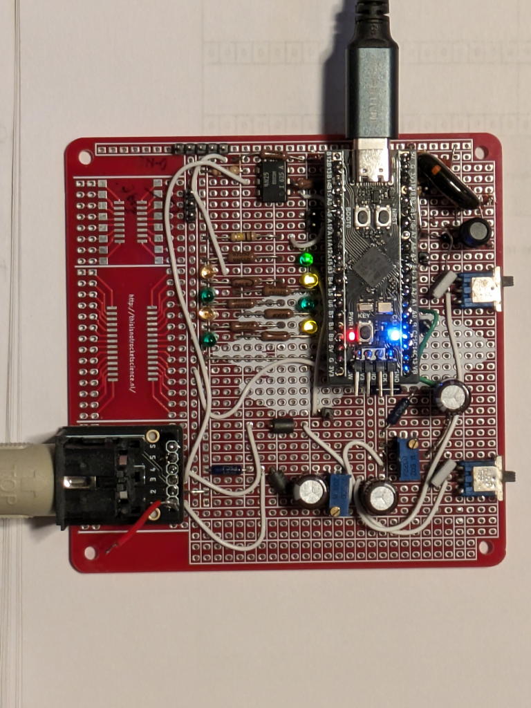
Here’s the “first article” engineering prototype. It contains some test circuitry which is not included in the sample schematic.
The OpenTNC is a simple but very functional TNC which can be constructed at low cost. It requires no exotic analog integrated circuits (e.g. modulators, demodulators, PLLs), just a microcontroller board and a handful of common components and connectors. It supports both KISS mode (for interfacing with PC-based networking stacks) and a traditional interactive “connected mode” of operation. It connects to a computer using USB, presenting itself as a class-standard USB “composite asynchronous communication device” (a “virtual serial port”), requiring no special drivers on Linux, Macintosh, and modern Windows systems. The command set is based on, and largely compatible with that of the TAPR TNC-2 and its clones.
The code used here is a new implementation of AX.25 - it was not derived from any existing TNC’s code, nor from Dire Wolf nor the Linux kernel implementation of AX.25. It runs on a simple “WeAct Black Pill 3.2” development board utilizing an STM32F411 Cortex-M4 processor. It should be largely portable to many similar boards (e.g. STMicroelectronics Nucleo), other ARM Cortex-M processors, RISC-V cores, and so forth. The code runs as an application on the open-source Zephyr kernel, utilizing standard Zephyr APIs and drivers wherever practical. A subset of the code can be run as a native Linux application, using the Zephyr “native_posix64” board definition.
A no-frills KiCAD schematic (with a number of possible parts-stuffing options) is included in the project.
Why in the world would anyone design and build yet another sort of 1200-baud packet TNC today?
“Narns, humans, Centauri, we all do what we do for the same reason: because it seemed like a good idea at the time.” (Ambassador G’kar, Babylon 5)
For the past couple of decades I’ve been participating in my city and county’s ARES/RACES organization. These groups have found it beneficial to develop a county-wide network of packet-radio BBS systems for passing emergency traffic in a time of need. Even at 1200 baud (a terribly slow speed by today’s usual standards) it’s possible to pass messages more quickly by packet than is possible via voice (simplex or via repeater). The packet group makes heavy use of the Outpost Packet Message Manager software originally developed by Jim KN6PE (see https://www.outpostpm.org/) and the PackItForms system (see https://www.scc-ares-races.org/data/packet/about-packitforms.html) to improve efficiency.
Participating in this network requires owning a TNC, and this is a significant issue for many operators. The choices are somewhat limited:
Full-function TNCs such as the Kantronics KPC-3+, the TAPR TNC-2 and its clones from e.g. MFJ, and so forth. These are well-tested and featureful. They’re not inexpensive if purchased new, and older “hamfest” models may not be reliable.
Reduced-function TNCs built into many higher-end VHF/UHF radios. These are “free” when they’re present, and often worth what you paid for them :-). They’re usually adequate for packet- spotting operations, APRS, and similar “fire and forget” tasks, but often have buffer-size limitations and/or protocol bugs which make their use in “connected” mode a very painful and frustrating one.
Simple microcontroller-based “KISS” TNCs, which handle transmission through the radio at the level of individual packets, but have no user interface and no built-in support for user-to-user connections. They appear to the PC as a simple serial port of some sort, “talking” a specialized packet-interchange protocol. These are often inexpensive, but performance of these KISS TNCs tends to vary greatly, depending on the sophistication of whatever hardware and firmware they use to perform the necessary audio modulation and demodulation. They must be used with PC software which implements the AX.25 “layer 3” connection protocols, packet acknowledgement and retransmission, and so forth.
There are several such software packages available such as AGWPE (WIndows) and the AX.25 network support built into the Linux kernel. Each of these requires some specialized knowledge and configuration to use.
“Sound card” TNCs. These are an extension of the “KISS TNC” approach, where the KISS TNC is a specialized application running on Linux or Windows, utilizing the PC’s sound hardware as an interface to the radio, and presenting a virtual “serial port” which speaks the KISS protocol. Once again, they require KISS-aware PC software which implements the higher levels of the AX.25 network stack, creates a user interface, etc.
The excellent Dire Wolf package (hi, John!) is a very-high-quality sound-card TNC combined with an AX.25 stack, and there are several sound card KISS applications available for Linux which work with the kernel’s AX.25 stack.
About ten years ago, I started wondering whether there might be a different approach possible today: a full-featured TNC (something roughly akin to a TAPR TNC-2) built using a modern high-performance microcontroller, using digital signal processing techniques rather than fancy (and often hard-to-get) analog ICs to do the modulation and demodulation. It could (potentially) be inexpensive, flexible, and relatively easy for an amateur operator to construct quickly and easily. The firmware could be made open-source, and might potentially serve as a platform for further experimentation. And, finally, it would give me a chance to play with the new generation of inexpensive, high-performance microcontrollers and development boards, learn some things, and make something at least vaguely useful.
1200-baud packet radio modulation isn’t complex. It uses audio frequency shift keying (AFSK), switching between two audio tones at 1200 Hz and 2200 Hz, transmitting and receiving a stream of bits encoded using the HDLC protocol. It’s based on the old Bell 202 telephone modem standard (and I imagine that the original crop of packet radio systems used repurposed Bell 202 modems). Transmitting (modulating) requires creating 1200 and 2200 Hz sine wave tones, switching between them as an HDLC bit stream is processed. Receiving (demodulating) requires distinguishing these two tones with accurate timing, and recovering the transmitted HDLC bit stream. None of these seemed to be beyond the capability of an inexpensive processor running at close to 100 MHz.
Early experimentation with algorithms running on Linux suggested that the audio processing could work, and writing the low-level HDLC frame encoding and decoding software wasn’t difficult. I was able to port one version of this code to run successfully on a $3 “Blue Pill clone” development board, and decode a test suite of packets from a standard recording, with the packets being sent via USB and KISS to my Linux workstation for analysis. I used the WA8LMF TNC Test CD data, tracks 1 and 2 as my primary test corpus.
The performance wasn’t what I had hoped for (especially on noisy signals or where equalization was an issue), and I put the project on the shelf for some years until after I retired. In the meantime I thought up some possible improvements.
A month or so of recent work has gotten things to a very usable state… what I consider good-to-very-good demodulation performance. Getting it there required moving up to a somewhat more powerful microcontroller (a Cortex M4 with hardware floating point support). In recent tests, the OpenTNC has successfully received between 976 and 980 packets from the WA8LMF track 1 recording.
In order to support easy “plug and play” compatibility with Outpost, and to eliminate the need for users to set up and manage AGWPE or Dire Wolf, it was apparent that basic AX.25 Layer 3 connection support would be needed. So, I sat down and wrote it. The OpenTNC implementation is targeted at the classic AX.25 2.0 protocol specification. I haven’t tried to implement the more complex features in AX.25 2.2 (e.g. protocol parameter negotiation, or SABM-E extended modulus support), although I did take a few simplifications from 2.2 where they made life easier.
The bill-of-materials cost for a working OpenTNC might run from $20 to $40, depending on what you decide to include, how you decide to order it, and how well your junk box is stocked. The essentials are:
A WeAct 3.2 development board, based on the STM32F411.
A 4N35 or similar opto-coupler, for the push-to-talk circuit.
A handful of common analog components - resistors, capacitors, a couple of trimpots, ferrite beads, LEDs, and an inductor. The values given in the schematic are suggested, and not terribly critical - feel free to experiment and improvise.
A jack for the connection to your radio. The schematic shows both a DIN-5 180-degree female (TNC-2 standard, often sold as a “MIDI jack”) and a DE-9 female (Kantronics standard). Feel free to wire up either or both (but don’t use both at once!)
Optionally, a pair of 1:1 audio isolation transformers (telephone or modem “line coupling” transformers are ideal). These are required only if you want separate, isolated grounds for the TNC and radio.
Some sort of prototyping board to which you’ll solder all of the above, and run jumpers as necessary.
The example schematic I’ve provided shows the components, and their interconnection. I’ve only drawn actual “wires” in a few places (the analog input and output circuits) so you’ll have to look at the signal names to determine the connections.
I’ll try to include an installable image file in this repo for each major version, so you won’t need to build the firmware yourself unless you want to. No promises.
To flash via usb:
dfu-util -D OpenTNC.dfu:leaveIf you do want to build it:
You’ll need to install the Zephyr kernel, and its associated SDK. Visit https://zephyrproject.org/ to learn about Zephyr and how it’s installed and used.
Install this firmware source tree into zephyrproject/apps/OpenTNC - I suggest using “git submodule” to do so, so you can easily track any changes and pull down new versions.
Do a “git submodule init” in the apps/OpenTNC directory, to fetch the libcorrect library code.
Build, with “west build -p -b blackpill_f411ce apps/OpenTNC”. This should compile and link the application, storing everything under the “zephyrproject/build” directory.
Flash the firmware image to your completed board, with “west flash”.
Zephyr, and this board support at least two ways of flashing an image to your board: via USB, or via an external probe hooked up to the board’s single-wire-debug (SWD) pins. You’ll need to configure Zephyr to know which flashing “runner” you want to use (see the documentation).
I can definitely recommend the BlackMagic Probe as a good development tool for a project like this. It supports flashing via SWD, it supports interactive debugging (running its own GDB-compatible remote server in the probe), and it provides an auxiliary UART which can be connected to the debug-console UART on the OpenTNC. You can buy a finished BlackMagic probe, or you can build one yourself from a cheap “blue pill” board (download the BlackMagic source code, build it using the “swlink” target, flash it into a Blue Pill, and solder on a few wires with Dupont connectors).
Many manufactures’ development boards (e.g. the STMicroelectronics Nucleo series) come with onboard debug probes which support SWD flashing. ST boards have an STLink, others have a CMSIS-DAP, etc. Vendor-specific software can be used with these probes, in order to flash firmware onto a target device.
Zephyr supports code flashing via USB DFU (Device Firmware Update). On the Black Pill, you can (sometimes) get into DFU mode by holding down the “BOOT” button, then pressing and releasing “RSET”, and then releasing “BOOT”. The Black Pill should enumerate on USB in DFU mode, and you can then
west flashor, if you’re using a pre-built .dfu image,
dfu-util -D OpenTNC.dfuA word of warning - the STM32F411 bootloader is notoriously prone to becoming confused if any of the interface pins it looks at are active, floating, or are being pulled in the wrong direction when it starts up. It mistakes these as an attempt to bootload from (e.g.) a UART, SPI, or I2C interface, and it fails to enumerate USB and present a DFU interface. I’ve struggled with this problem extensively when working with my prototype board. I think I’ve included enough of the proper pull-up and pull-down resistors in the sample schematic to avoid the problem, but as I haven’t yet built a board in this style I can’t be certain.
If you can’t get the board to enumerate properly on USB, you can try unplugging the WeAct board and flashing it stand-alone - that sometimes works. If not, you’ll have to use SWD flashing, using a BlackMagic probe, an ST-Link v2 or one of the cheap clones, etc.
The OpenTNC enumerates as a USB composite device, supporting a CDC-ACM “virtual serial port”.
The OpenTNC should be “plug and play” on any reasonably recent Linux system, as generic CDC-ACM support has been in the Linux kernel for years. The device will appear as (e.g.) /dev/ttyACM0. A udev rule can be used to give it a more interesting (and permanent) name, such as /dev/OpenTNC.
I understand that recent versions of MacOS will also recognize such CDC-ACM devices as virtual serial ports, without any specific drivers being required. I haven’t tried.
Similarly, Windows 11, and newer versions of Windows 10 will also recognize CDC-ACM devices and use a generic built-in “USB serial port” driver. I’ve tested this successfully on a Windows 10 system.
Windows 7 requires a device-specific .inf file in order to use the generic “USB serial port” driver.
Windows 8 requires a signed device-specific .inf file, which I have no ability to write and sign. If there’s anyone out there who has a Windows driver-signing certificate, and is willing to contribute a suitably-signed .inf to the cause, I’ll be glad to distribute it!
Once built, flashed with the firmware code, and reset, your board should enumerate on USB as a “OpenTNC” and a CDC-ACM “virtual serial port” should appear. You can connect to this using ’most any terminal-emulator program (baud rate doesn’t matter), and the TNC command prompt should appear.
Type “help” to get a list of commands supported.
Remember to set your callsign (with “MYCALL xxxx” followed by “SAVE!”) before connecting the TNC to your radio and trying to transmit.
To use KISS mode, connect to the TNC as above, wait for the prompt,
and send the command “KISS ON”. The TNC will switch to KISS mode
immediately. To exit from KISS mode, either cycle the power, or send the
KISS exit sequence (0xC0 0xFF 0xC0) to the TNC, or (on Linux, if you
have the interface up) incant kissparams -x $PORTNAME
The OpenTNC is designed to operate with the squelch open. It “detects carrier” when it successfully locks onto the HDLC bit-stream from a demodulated signal - one of the LEDs goes on when HDLC is locked in. Two flickering LEDs show the bit values coming out of the demodulator. Another LED flashes briefly when a good packet is decoded. Two other LEDs glow to indicate “demodulator busy” and “modulator busy” - you can measure the duty cycle of these with an oscilloscope if you want to see how much CPU time is being spent doing the necessary digital signal processing.
The analog signal pathways are straightforward. The incoming signal simply goes through an attenuator potentiometer and an AC-coupling capacitor, is biased up to half of the board’s 3.3-volt rail, and fed through a GPIO pin to the analog-to-digital converter. The signal is sampled 38400 times/second, filtered down to 9600 samples/second, and then fed to one of several different demodulator algoriths. Not a lot of signal is required - I see good, solid 1-versus-0 discrimination with as little as 30 millivolts peak-to-peak, and up to 1 volt peak-to-peak is OK (the “clip” LED will flash if the level is too high). The default receive algorithm (demodulator 4) is based on a chain of floating-point biquad bandpass filters, and has been the most effective one I’ve tried out so far. [Actually, it’s the most effective three I’ve found. It consists of three complete sets of filters with different equalization characteristics, and three independent HDLC decoders running in parallel. Kinda crazy but it really does seem to work well!]
The transmit pathway is a bit more ornate. The STM32F411 doesn’t include a digital-to-analog converter section, and I didn’t want to require the use of an “outboard” DAC chip, so it’s necessary to simulate one with a digital output and a low-pass reconstruction filter.
The filter creates a transmission-quality analog sine wave from the output at a digital GPIO pin being switched at a high frequency (either pulse-width or pulse-density modulation). The filter I’ve chosen to use is a three-pole RCLC design, with -3 dB points in the 12 kHz - 15 kHz range. I don’t claim that this filter design is optimal; feel free to experiment. The signal then goes through a DC-blocking capacitor, and a potentiometer to set the output level to what the transmitter you’re using requires.
There are two different modulators available to create the digital output signal. Modulator 0 uses fast pulse-width modulation, based on one of the STM32F411’s internal timers/counters. The timer runs with a period of around 2 MHz, and has a duty cycle which varies along with the desired sine-wave amplitude. Modulator 1 uses first-order delta-sigma modulation, emitting a precomputed bit stream at 1.5 MHz using the chip’s SPI peripheral module. By good fortune, both of these outputs can be routed to the same pin, so only a single set of low-pass circuitry is needed to reconstruct a decent sine wave from the chosen modulator.
The OpenTNC supports the simple KA9Q “KISS” mode of operation (including support for SMACK checksums on the KISS packets). This allows you to use the OpenTNC with AGWPE or Dire Wolf or the Linux kernel’s AX.25 stack, if you should so desire.
A more traditional interactive “connected mode” is also supported, using the OpenTNC’s own (new) implementation of this protocol layer. I’ve tested this software for interoperability with a couple of traditional TNCs (an MFJ-1270 clone of the TNC-2, and a Kantronics KPC-3), with the Linux kernel AX.25 stack (using the KPC-3 as a KISS interface), and over the air with the JNOS BBS, all with good results. I don’t claim that this layer is completely conformant or perfectly implemented but it seems to work well in practice.
The OpenTNC has the ability to randomly damage HDLC frames during
transmission and/or reception (corrupting the FCS so that the frame
fails to validate). This allows testing to simulate frame loss due to
noise, interference, or on-air packet collisions, and permits exercising
of the error-recovery ability of the higher layers in the stack. The
droprx and droptx commands can be used for
this purpose, e.g. droprx 7 will corrupt and drop roughly 1
incoming frame out of every 7.
I’ve successfully performed some long file transfers between OpenTNC and the other TNCs, with “damage ratios” as high as 1-in-4 (one way at a time) and 1-in-6 (with both transmitted and received frames being vulnerable to damage). The OpenTNC was able to maintain the connection even in the face of such high frame loss rates - there were a lot of REJ frames and retransmissions, but the data did get through.
Both KISS and connected-mode operation utilize P-persistence when transmitting. I have not implemented the older-style “fixed transmission delay” approach.
Data flow control is implemented in both directions. The TNC will
stall the USB “serial port” interface if you try to send data faster
than the peer can keep up - this has the same effect as traditional
“hardware flow control” on an RS-232 serial port. Similarly, if your
host software fails to read incoming data from the USB “serial port”,
the TNCs internal buffers will fill up and the TNC will start sending
RNR to the peer until the host catches up with the data. RNR can be
forced during testing… RNR 64 will stall roughly every
fourth set of incoming packets for a few seconds, RNR 128
will stall roughly every other set of packets for a longer period of
time, and RNR 0 eliminates the forced stalls.
There is (so far) only limited support for digipeaters. There’s no specialized support for APRS. Only a single connection at a time is allowed - there’s no support for STREAMSW.
Signal-present (and thus don’t-transmit-now) detection is based on the presence of HDLC lock. This works well for either open- or closed-squelch operation, but only as long as 1200-baud AFSK-on-FM is the only modulation in use on the channel. The current design won’t “see” voice, other modulation schemes, etc. as evidence of the channel being busy. Adding audio-level-based presence detection (for closed-squelch operation) and for a radio’s “RF detected, squelch open” voltage signal are TBD.
There’s no real support yet for 9600-baud packet operations. It’s not impossible by any means, but would probably require running the input and output sections at a 4x-higher sample rate. A different signal output path would also be required, feeding data directly to the FM radio’s modulator.
The example schematic shows a simple version of the OpenTNC, with a number of options available to the builder.
You can use either a TNC-2-style or Kantronics-style radio jack.
The schematic shows an ARM-standard 10-pin debug-and-programming connector, wired up to the Black Pill’s single-wire-debug pins. You can omit this connector, and the connection to the Black Pill entirely, and simply solder a 4-pin right-angle pin set to the Black Pill to access these pins (a suitable set of pins is usually included with the Pill), or omit this connection entirely if you don’t need flash-and-debug access.
The schematic shows a USB B jack, connected to the Black Pill’s D+/D- pins through 10-ohm resistors. You can omit all of these if you intend to mount the Black Pill in an orientation which allows you to connect a cable to its onboard USB C jack.
The schematic shows two separate “grounds” (TNC-and-computer, and radio) and the use of two line-coupling transformers to isolate the TNC-and-computer ground from the radio ground. In many situations this isolation is unnecessary. You can build the TNC with a single ground, omitting the transformers, and connecting the audio signal circuits directly to the “TX audio” and “RX audio” pins on the radio connector. The schematic includes “closed” jumpers which make these connections - you’d need to open these jumpers if you include transformers in your design.
I’ve included a sample board design with the sample schematic. This quick-and-dirty board is simply a manufactured-PCB version of a prototype board, with connection points for the Black Pill. It fits in a 10 cm x 10 cm boundary, which is one which many of the online PC-board houses will make quite inexpensively. It’s a four-layer board with internal ground and power planes - this requires less fiddly vias than a two-layer board would, and the increased board cost these days is minimal.
Please do not just go ahead and manufacture this PC board without extensive checking. I haven’t made one yet and there may very well be errors or incompatibilities. In particular, the connector footprints I chose may, or may not match up with whatever USB and DE9 connectors you can actually acquire, and the surface-mount transformer footprints are for a model which is probably obsolete and unavailable. Use it as a starting point, modify as required to suit your chosen connectors and components, and check everything before you make any.
A fancier version (better suited for mass production) would eliminate the Black Pill, and put down a “bare” STM32F411 or similar processor and the oscillators, capacitors, switches, and regulators it needs to operate.
One demodulator I haven’t yet tried is a digital phase-locked loop.
It wouldn’t be difficult to add DAMA-slave capability, so that the TNC would honor a “You are connected in DAMA mode” response from the remote peer (DAMA master), and would transmit only immediately after being polled by the master. Unfortunately I lack access to a DAMA-master system to use to test out this mode.
The code is currently running on a WeAct Black Pill 3.2 board, which uses an STM32F411 processor running at 96 MHz.
Most of the higher-level code (console/converse, Layer 3 and connection, and demodulation) should be quite portable to different boards and/or processors, as most board-specific details have been abstracted out. The signal baud rate, tones, and the audio sampling rate (38400 samples/second) would require some effort to change.
Most GPIO accesses have been abstracted through the Zephyr device tree and GPIO APIs, and the board-specific Zephyr device tree overlay. GPIOs can be reassigned by changing the overlay.
Other boards with this processor should work but you may need to write a new board-definition overlay to deal with GPIO pinout differences. Other processors may work but you may need to clone and modify the processor-specific board-driver file to account for hardware differences. At minimum, you’ll probably need a processor which has at least 128k of flash, at least 64k of RAM, 80 MHz or above, and hardware floating point support (e.g. a WeAct Black Pill 3.0 using an STM32F401CC might well work OK). If you decide to start with a different board or processor, I’d recommend picking one on the Zephyr “supported boards” list, as much of the work will already have been done for you.
The cheap Blue Pill family (STM32F103 and various clones) has insufficient RAM.
The RP2040 (as used in the Raspberry Pi Pico) has plenty of flash and RAM, but it has no hardware floating-point support. It should be fast enough for the preferred demodulator to run successfully using software floating-point, but I have not tested this. On the 96 MHz STM32F411, using software floating point requires about 2/3 of the processor CPU cycles to run the demodulator; the RP2040 has a faster clock rate and its Cortex-M0 core may be fast enough for the job.
The actual details of the low-level signal capture (receiving) and creation (transmitting) are somewhat board-specific. The Zephyr driver for ADCs doesn’t support timer-based sampling, or the asynchronous transfer of samples to memory via DMA, so I had to implement this using the low-level STM32 ADC and timer and DMA APIs. Similarly, the logic to feed sample values to the timer PWM block during transmission (PWM modulator) and to send delta-sigma bit sequences through the SPI block, are board- and system-clock-speed specific and use low-level APIs and ISRs. For any significantly different board or processor, it will probably be necessary to copy the “board_stm32f411.c” file, hand-modify the hardware-specific details, and change the CMakeLists.txt file accordingly.
The delta-sigma bitstream used by modulator #1 is tied to the SPI
data rate (currently 1.5 MHz), and would need to be recomputed to
support a board or processor with a different SPI data rate. See the
gentable-simple.c program in the noiseshaping
directory. You can modify the constants in the code to specify a
different system clock rate, clock divider, etc. and then run the
program to create a new noiseshaping_data.h file for your new
platform.
At some point I’d like to change the build process so that many of these clock-rate-specific features are handled automatically at build time. For example, the noiseshaping and PWM data could be computed during each build, based on the chosen board’s configured system-clock rate and SPI divisor. Doing this will require more knowledge of cmake, and the Zephyr build process than I currently possess.
Parameters are saved on command into the microprocessor’s internal flash memory, using the Zephyr flash driver APIs. The board device-table overlay is used to specify one of the predefined partitions in flash to use for this. The flash holds multiple sets of saved parameters, with the most recent (highest revision number) being loaded on startup. The partition selected for parameter storage is erased only when it’s entirely filled up with saved-parameter sets, and there’s no room for another. If you choose to port to a board which has a flash layout incompatible with this approach, you’ll have to figure out a different method of managing parameter storage (maybe a small SPI flash chip?)
It would be interesting, in the future, to use a platform such as this to explore the possibility of using different sorts of on-the-air modulation. One obvious possibility would be to use some form of multi-carrier orthogonal frequency division multiplexing (OFDM) such as was used by the Telebit Trailblazer modems of the early years of the Internet. Layering AX.25 frames inside of some form of forward error correction (convolutional code, Reed-Solomon, etc.) and then modulating them with OFDM might be a way of significantly increasing radio-channel throughput over voice-grade FM channels. I’m not sure whether a single-core Cortex-M4 would have the horsepower to do this, but it’d be an interesting experiment to find out!