Several people have asked me for detailed drawings and wood-cutting instructions for my enclosure, and for details on the crossover design I used.
Unfortunately, no actual drawings of the enclosure (and the pieces of MDF I cut to make it) exist. I did a bunch of very rough sketches of the design, but didn't bother to save them, and I've never bothered to actually plug all of the design numbers into a CAD/CAM program to create a set of diagrams. Due to the complexity of the enclosure (with its 4- and 15-degree angles all over the place), doing a meaningful set of cutting diagrams or an "exploded" assembly diagram would be a very laborious process, and I haven't wanted to spend the time to do such a big job.
What I do have, is a multi-page MathCAD worksheet which shows (and, in fact, re-creates) the thought processes and calculations I went through while doing the design. It has a fair bit of commentary scattered throughout the calculations (I found that it helped a lot in keeping my thinking and figuring straight), and should permit the intrepid DIY'er to recreate my cabinet or to calculate a similar one.
You can download a PostScript version of this worksheet here and then view it with GhostScript or send it to a PostScript-capable printer to create a hardcopy.
As to the crossover design I used: unfortunately, this is the one aspect of the system that I'm not free to talk about in detail. In return for doing the measurement and customization work at no charge, Brian Smith of Just Speakers asked me not to publish or redistribute the schematic of the modified Signature 717 crossover he provided to me. He'd done a lot of work to develop and tune the Signature 717 crossover, and didn't relish the thought of having his work-product "cloned" by other kit sellers.
I felt his request was quite reasonable, and agreed to it. Since then, I've been referring people who are interested in this design directly to Brian. Unfortunately, Just Speakers is now out of business, and I don't know of any way to contact Brian to discuss the issue.
One possible alternative source for a crossover of this type is North Creek Music Systems. Their Rhythm design is quite similar to the Signature 717. It uses the 18W8545 carbon-fiber drivers, and one of several different Scan-Speak dome tweeters (the Revelator is available as an option) in a ported-cabinet MTM arrangement. The kit design, including cabinet plans and a complete schematic of the crossover, is available from them for a modest fee.
Solen and Madisound are also possible sources for a crossover for this sort of system. Both companies will calculate a crossover for your choice of drivers, for a modest fee (usually in the $50 range).
Another alternative comes from Navin Advani, a member of the DIY Speaker Builder mailing list for quite some time. Navin has built several speaker systems based on the Scan-Speak 18W8546 and Revelator drivers (the same ones used in the Signature 717). Working with other members of the mailing list, Navin has developed two different crossover circuits for an M/T/M speaker using these drivers, and one circuit for an M/T speaker system using an 18W8546 woofer and a Scan-Speak 9500 tweeter. I rather expect that Navin's crossover circuits would work well with the 18W8545, too, as the two drivers are fairly close cousins. However, I haven't actually tried them in my system, and so can't give any first-hand information about how they compare to the crossover design I used.
Navin has quite kindly given me permission to post his crossover designs on the Web.
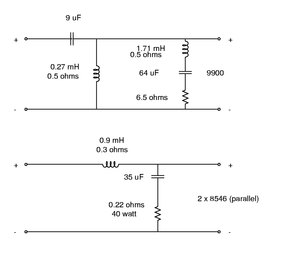
Drivers: 2x 8546, 1x9900
Cabinet: 7.5"x20"x21" (approx)
Woofer circuit: Series inductor 0.9mH, followed by parallel 35uf cap and 0.22ohm resistor
Tweeter circuit: 9uf series cap, followed by parallel 0.27mh inductor and parallel notch filter using 1.71mH, 64uf and 6.5 ohms
This circuit uses an oversized inductor (having extra taps at 0.8mh, 1.0mh and
1.1mh) for the woofer for diffraction control and notch filter for the
tweeter since the XO slope is only about 12db/oct.
The inductors were all hand wound using 12AWG (14SWG) copper wire using a
lathe machine. The caps were polyester, with the values larger than
10 uF being made from multiple smaller caps in parallel. Capacitor
values were hand-matched to within 1%.
This is the crossover I use. However I find
that it is not as detailed as the second crossover described below,
although the balance is a bit better. My
project when I get back to to combine the features of both XOs.
Drivers: 2x 8546, 1x9900
Cabinet: 7.5"x20"x21"
Woofer circuit: 1 mh series inductor followed by 12uf parallel cap and followed by 1 mh series inductor
Tweeter circuit: 4.7uf series cap followed by 0.35mh parallel inductor followed by 24uf series cap
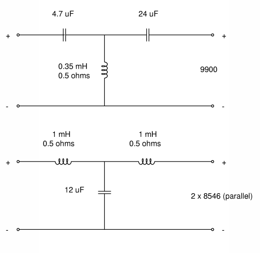
This circuit uses the T topology for the woofer inductor instead of a
single large cap to roll off the woofer. The tweeter slope is effectively
about 18db/oct hence it was felt that no notch filter is required as the
level would be over 36db down at the impedance peak freq of the 9900
tweeter (500Hz).
This circuit was made for a full-range MTM (designed using Calsod mostly by Thorsten)
with a Valve amp in a well padded room. This installation made most speakers
sound dull (like the tweeeter was blown) and hence it makes the 8546-9900
sound bright in any other room. With this circuit the system is very
detailed and a bit lean.
Given my room conditions, I have found this circuit to be a bit more
forward than the above circuit. This makes the sound more dynamic. My
friends prefer this XO but I prefer the earlier XO.
Drivers: 1x8546, 1x9500
Cabinet: Hexagonal pyramid having base 9" wide and height about 20"
Woofer circuit: 2.2 mH series inductor followed by series combo of 18uf cap and 2 ohm resistor in parallel with driver
Tweeter circuit: 6.8 uf series cap followed by 0.7mh parallel inductor and level matching circuit using 4ohm series resistor and 15ohm parallel resistor. The tweeter is connected with its normal polarity reversed!
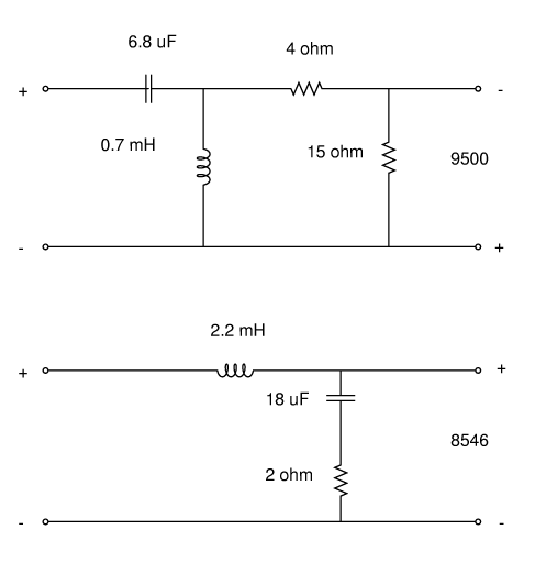
Note that the effective impedance seen by the reactive components in the
tweeter circuit is about 9ohms (ok ok 9.2 ohms if the 9500 is
approximated by a 8 ohm resistor).
Here again the 2.2 mH inductor has a tap at 2.5mH and the 0.7 mh
inductor has taps at 0.5 and 0.3 mH. The 18uf cap was replaced by a
23uf cap and then re-replaced by the 18uf cap. The 2 ohm resistor was
replaced with a 1 ohm resistor and re-replaced with the 2 ohm
resistor. I have also found that as far as level matching circuits go
a large parallel resistor can damp a shallow impedance peak. I
prefered the sound the 15 and 4 ohm combo to a 10 and 3 ohm combo.
The tweeter is connected with its normal polarity reversed. This is
quite common for second-order crossover circuits such as this, because
the low- and high-pass crossover circuits each introduce a 90-degree
phase shift in the signal at the crossover frequency. If the tweeter
is connected with normal polarity, the two 90-degree phase shifts add
up to 180 degrees, causing the woofer and tweeter signals to be 180
degrees out of phase at the crossover frequency, and a very audible
"suck-out" occurs (there's a deep notch in the system's frequency
response). Reversing the tweeter polarity eliminates the suck-out.