Well, a lot of time has gone by since I last posted an update to this project. For most of that time, nothing changed with the system itself.
What did change was my level of satisfaction with it. Over the years, I found that I was perceiving the system as having more of a “forward” sound characteristic than I preferred - it was too bright, and lacking in warmth. The crossover modifications I’d made in the early days had reduced this somewhat, but it was still there. As I’ve gotten older, I think my ears have grown less tolerant to this sort of excessive brightness.
In recent years I had done a couple of other speaker-related projects and had installed two other stereo systems in my house. One (in my work office) uses a pair of Minimus 7 speakers, which I had rebuilt using the open-source PZ-2.1 crossover design, and an Onkyo subwoofer. The other (in one bedroom) uses a pair of Mission 700 Leading Edge bookshelf speakers (rebuilt the crossovers) and a Definitive Tech subwoofer. I had acquired a good, well-calibrated measurement microphone (a uMic-2) and some knowledge of Room Equalization Wizard to measure and optimize these.
What I found that I was enjoying music more, listening to it on either of these modest systems, than I was when I listened to it on the big living-room system. The overly-forward character of the system I’d built decades ago was clearly second-rate in my ears.
I decided that this Simply Shouldn’t Be, since the drivers and construction I had used in the MTM design were of high quality and ought to be capable of delivering more musical results. It was time to sit down and analyze the problem and figure out what to do.
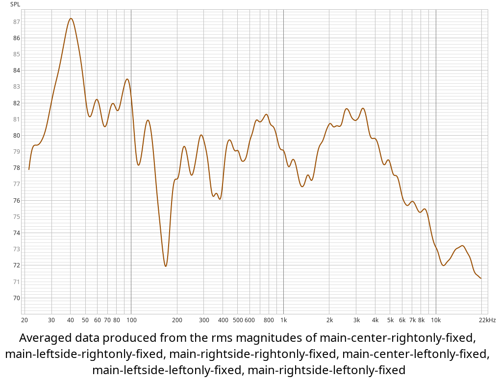
Earlier this year I used the uMic-2, and Room Equalization Wizard to perform sweeps of the living room system’s frequency response and distortion. I took multiple readings, from three different listing locations, and averaged them together to get an overall look at the situation.
The results were enlightening. Houston, we’ve had a problem.
The bright-but-lacking-in-warmth problem shows up pretty clearly here. There’s a broad peak of several dB centered up at 3 kHz, a second smaller peak centered around 700 Hz, and quite a dip between them. Also, the crossover between the MTM and subwoofer sections shows a deep null right around the crossover frequency, and there’s a big room resonance at around 40 Hz.
The news wasn’t all bad, by any means. One pleasant result was that the overall frequency response of the system was not very sensitive at all to the measurement (listening) position. Apparently, the trick I had used when designing the cabinets (aiming the front bezels inwards slightly), combined with the wide and consistent dispersion pattern of the Scan-Speak tweeters, had worked as I had hoped. The other good result is that the “grills on” and “grills off” measurements were nearly identical - the grill assemblies were not altering the sound significantly.
Lesson the first: good measurements are essential to understanding.
After I looked at the graph of the midrange response for a while, it began to look a bit familiar, and I went back and pulled up the data sheet for the Scan-Speak 18W8545 midwoofer drivers I used.
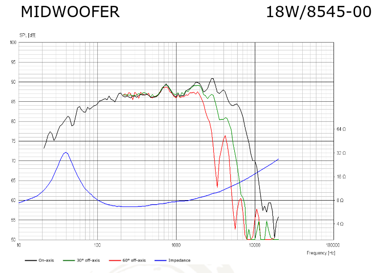
Aha! The manufacturer’s data shows the same sort of rising response and unevenness in the midrange - that’s probably the source of at least part of what I’ve been hearing. I had assumed that the Just Speakers crossover’s characteristics would compensate for this - and I’d been wrong.
Lesson the second: don’t assume.
It’s possible that this isn’t the only source of the ragged frequency response. There might be some resonance effects inside the MTM sub-enclosure, I suppose. There’s a good deal of long-hair wool damping material in there, but it might not cure all ills.
So, it looked to me as if I had several issues to deal with here:
I needed to flatten out the frequency response in the midrange, getting rid of the influence of those two peaks I measured.
I should try to improve the integration between MTM and subwoofer in the crossover region.
I should do something to tame the 40 Hz room resonance.
I figured I could probably tackle the first issue by adding some series traps to the existing MTM crossover. This would be tricky, and probably expensive, as I would need two RLC traps with fairly large inductors and high-quality capacitors per speaker, and I’d certainly have to do a bunch of cut-and-try construction and many cycles of measurement. This didn’t seem like an easy or attractive approach.
I could scrap the existing MTM crossover design, and re-design from scratch. This would require doing careful measurements of the drivers as installed in the cabinet - both impedance measurements and near-field sound-pressure measurements would be needed. I now have the equipment needed to do this (I’d built an impedance-measurement jit for use with the Scimpy), and I could disconnect the existing crossover circuitry on the rear of the cabinet and access the individual driver connections without opening the cabinet. However, this approach would also probably require a bunch of “cut and try” simulation and experimentation, could very well require replacing many of the (fairly expensive) crossover components I’d been using, and might end up with a very complex crossover being required - I’d still have to “trap out” those two peaks, in one way or another.
I could change the crossover frequency between MTM and subwoofer by replacing resistor packs in the Marchand crossover. I wouldn’t be able to change the crossover slopes, and I couldn’t do anything about the 40 Hz room resonance.
I was also suspicious that some of the MTM-to-subwoofer null might be caused by the fact that there’s a significant phase difference between the MTM and subwoofer. The acoustic center of the (side-mounted) crossover lies almost a foot behind the acoustic center of the MTM driver. I wouldn’t be able to compensate for this at all with the Marchand crossover.
So, I decided to try a different approach:
Leave the existing MTM passive crossover entirely unchanged. It does what it was designed to do (handle the MTM-to-tweeter transition) quite well.
Replace the Marchand active crossover with a miniDSP 2x4HD. This is a high-quality “two-in, four-out” signal processing engine, capable of implementing many different crossover and equalization configurations. It supports many standard crossover formulas, and each channel has a bank of biquad filters capable of implementing many different filter types and widths. I’d start out by re-creating the same basic crossover configuration I was using with the Marchand, and work from there.
In the miniDSP configuration, add a millisecond or so of time delay to the MTM signal path, compensating for the acoustic-center offset.
Use the miniDSP biquad filters to correct the 40 Hz room resonance (in the low-pass signal path), and to carefully flatten out the peaks in the MTM midrange response (in the high-pass signal path).
I changed out the crossover, configured it to mimic the configuration of the Marchand, and re-measured the system (both as a whole, MTM-only, and subwoofer-only). I was pleased to see how low in frequency the MTM arrays actually work - they’re got good output down to around 80 Hz. This is rather better than I had expected from my cabinet modeling and the driver parameters. My guess is that some acoustic reinforcement from the wall behind the speakers is (by good luck) compensating to some extent for the drivers’ natural rolloff in this cabinet, and extending their response below what a free-field measurement would show.
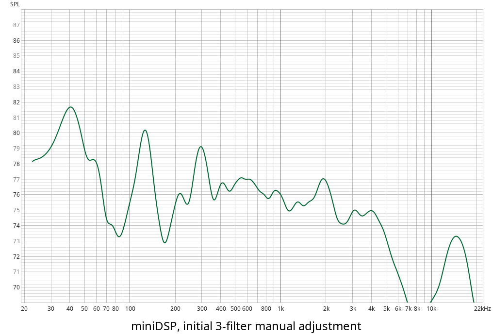
I used REW’s EQ interface to develop an initial set of “flatten out the midrange peaks” filters, using the miniDSP biquad filter system. The first version used three low-Q “peak” filters, with a few dB of negative gain; I tuned them “by eye” based on REW’s prediction for the result.
I then loaded equivalent filter settings into the miniDSP, and gave the updated system another round of measurement and some listening tests.
My first impression of the change was a very positive one. The “glare” which had troubled me was very much reduced, and the system had a significantly warmer and more musical character. The measurements I took showed that the midrange had flattened out as predicted. Not too bad for a first stab at the problem.
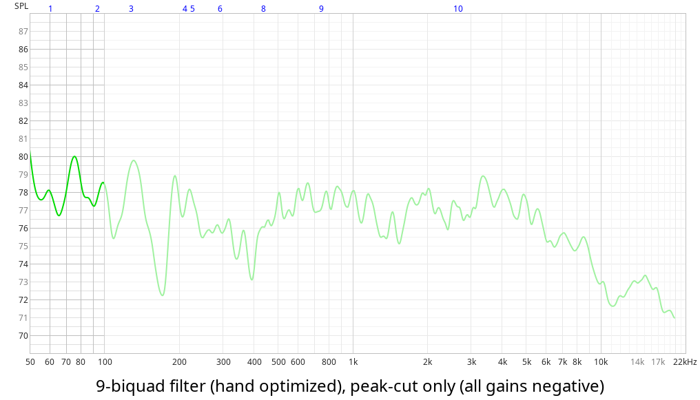
I’ve done some further optimization since then, based on the newer set of measurements:
I tweaked the initial filter settings, substituting two or three smaller (often overlapping) peak-cut filters for each of the original ones. I added several more peak-cut filters to the collection, gently flattening out smaller peaks in the midrange. I ended up with 9 biquad filters for each MTM.
Rather than port the filter settings over to the miniDSP software individually, I used REW’s ability to export the filter biquad coefficients, and imported these into the miniDSP configuration directly.
I added a peak-cut filter at 40 Hz to the low-pass (subwoofer) signal path, compensating for the 40 Hz room resonance.
I moved the subwoofer-to-MTM crossover point down to 100 Hz, and played with the individual turnover frequencies and Q to minimize the 150 Hz interference “dip”.
The filter predictions look good, and I was quite pleased by the resulting sound. I haven’t yet taken the time to fully re-measure the system with this filter set in place.
The results, for the past six months, have been quite satisfactory. The overall musical tone of the system is definitely superior to what it was a year ago. It’s clear and clean, not shrill or honky or bright or forward, and very pleasant to listen to. I think it’s finally delivering the sort of musical experience that its drivers are capable of.
I haven’t made any attempt to use equalization to “boost my way” out of the remaining null at 150 Hz. I know that’s a poor idea. Its impact on the music seems to be very limited, and I don’t want to mess up the system’s transient and phase response in this frequency region. I plan further experimentation in this area to see if I can reduce the depth of this null; this may not be possible if it’s due to floor-reflection cancellation effects.
I wish I had had access to wonderful technology like REW and a good calibrated measurement microphone when I first built the system, almost three decades ago, but such things were expensive beyond my means back then. We definitely have better tools available nowadays, for prices that yesterday’s technologies couldn’t approach.
When my wife and I bought a house back in 1995, I made her a couple of promises about the living room. One promise was to get rid of the ugly black 19” EIA equipment rack in which I’d installed our stereo equipment, and replace it with some type of cabinet that fit into the room’s decor. Another was to replace my then-current speaker system (a pair of Fried B/2 satellites, with a Fried T subwoofer cabinet the size of a coffee table) with something a bit less visually intrusive.
I fulfilled the first promise by having a local cabinetmaker design and install a set of shelving and cabinets... an “entertainment center” they call it... in the industry-standard white Melamine. This holds the TV, the VCR, the stereo electronics, and has storage space for tapes. The whole stereo can be concealed behind closed doors when not in use.
The speaker system was a bigger job. I wanted something which sounded at least as good as the Fried system I’d be replacing, and which would be as close to “invisible” as possible. I looked at some commercially-available systems, but those with sufficiently good sound quality didn’t come in sizes or finishes which would fit well into the decor and space in our living room. Nor was I eager to spend $5000 or more, to buy a system I knew I’d be happy with for years.
I’d built several speaker systems from kits over the years (the Fried systems, a set of Madisound Sledgelings for my office, and a set of Speakerlab systems back in my college days). I checked the current kit-offerings from several speaker companies, and saw quite a few interesting ideas, but nothing which really seemed to fit what I wanted. I decided to see whether I could design something from scratch.
I spent the next few months doing research - buying and reading Vance Dickason’s Loudspeaker Design Cookbook, signing up for the BASS mailing list and reading its archives, and digging through a nearly-complete collection of back issues of Speaker Builder magazine. After much study and discussion, I decided to build a system with the following basic characteristics:
Getting all of these characteristics into one set of cabinetry proved to be somewhat non-trivial. The NHT 1259 subwoofer requires about 3 cubic feet of enclosure volume to deliver a near-flat response. With 1 cubic foot for the MTM subenclosure, the volumes of the drivers, the subenclosure walls, braces, etc., I figured I’d need close to 4.5 cubic feet of cabinet volume. A simple rectangular cabinet with this volume would either be too wide (front baffle wider than desired), too tall (wouldn’t fit under the mantlepiece) or too deep (would stick out too far).
I decided to use a trapezoidal cabinet, with the following approximate dimensions: front baffle 9” (rotated inwards 15 degrees, tilted back 4 degrees). Rear wall 15”. Inner side 20” (perpendicular to the rear wall, meeting the front baffle at a 105-degree angle). Outer side 24” (perpendicular to the front baffle, thus meeting the rear wall at a 75-degree angle). Height 40”.
The trapezoidal shape, and tilted baffle used in this design meant that most of the pieces of MDF used in construction would not be simple rectangles - they’d have cuts at odd angles, in one or both axes and on one or more edges. I spent quite a bit of time plugging numbers and formulae into MathCAD, calculating the actual dimensions of each piece and double-checking the resulting fit and cabinet volumes. If you want to see the calculations, follow this link.
I decided to sanity-check the design before I started cutting wood. I built a 40% cardboard scale model... by measuring 1 cm of cardboard for each inch of MDF, the calculations could be checked pretty easily. The cardboard model went together successfully, with no big ugly gaps, so I had some degree of confidence that the physical universe was willing to correspond to my theoretical calculations (or vice versa!).
During the week after Christmas 1995, I started buying and cutting wood. Our local hardware store (Orchard Supply) sells 24”-by-48” sheets of 3/4” MDF for under $10 - this size was quite convenient for my use, given the dimensions of the cabinet I’d decided upon. Actually, I’d set the limit on my cabinet size in part to ensure that I could use these MDF sheets.
I don’t own, or have convenient access to a table saw or radial-arm saw. I do have a circular saw, a portable jigsaw, a router, and a reasonable collection of hand tools. Cutting these odd-shaped pieces of MDF using only these tools proved to be an interesting challenge. I constructed a good straightedge out of some pine 1-by-2, measured every cut at least twice before cutting, and became very familiar with the cutting-angle adjustment on the circular saw. By care, and with more than a small amount of good luck, I only messed up a couple of cuts, and was able to recycle the mis-cut pieces of MDF at a later stage in the construction.
You may hear people tell you that to cut MDF properly, you should invest in carbide-tipped saw blades, router bits, etc. Believe them. High-speed steel does go dull quite quickly when cutting MDF... I wore out two circular-saw blades and a router bit learning this lesson. You’ll save money, do a better job, and (most importantly) work much more safely with carbide blades and bits.
The cabinets were assembled using a combination of screws, glue, and 2”-by-2” pine cleats in the corners. I started out using carpenter’s glue (the yellow aliphatic type). Due to a combination of the odd cutting angles required, the lack of a table saw, and my own limited skill at precision cutting, I found that some of the interior pieces weren’t cut precisely enough to allow for gap-free joints. For this reason, I stopped using aliphatic glue, and switched to a low-viscosity slow-cure marine epoxy (with a silica thickener added as necessary) for the rest of the construction. This particular epoxy blend (TAP Plastics) fills gaps quite nicely, is very strong, and isn’t a strong skin sensitizer.
The subcompartment for the MTM drivers takes up the upper front quarter of the total cabinet. Its back is defined by a piece of MDF about a foot wide and 24” high glued to the sidewalls, 6” behind the front baffle. Its bottom is defined by a trapezoidal piece of MDF which extends all the way from the front of the cabinet to the back; I cut a large hole in the rear portion of this bottom piece, so it acts both as a sealed bottom for the subcompartment and as a sort of H-brace for the rest of the cabinet.
The remaining L-shaped area of the cabinet is dedicated to the NHT 1259 subwoofer. I used a router and a radius jig to cut the necessary opening in the side panel. The woofer opening is slightly recessed - not enough to allow the driver to sit entirely flush with the surface (this would have thinned down the edges of the mounting hole too much).
The front baffle was probably the most complex single piece of work required. I had decided to make it double-thick, in order to provide a rigid and well-damped support surface for the MTM drivers. The rear piece was cut to the size of the cabinet front. The front piece was cut 1.5” undersize in each dimension (plus a fraction of an inch more undercut horizontally to take into account the narrowing of the baffle). I cut 3/4”-radius pine “quarter-round” to match the dimensions of the front piece, trimmed the ends to a 45 degree angle using a miter box, and glued them around the edge of the front piece using epoxy and strap-clamps... thus creating a nice chip-resistant rounded edge to the front baffle.
I then marked and routed holes for the drivers in the front and rear baffle plates. The front plate was routed to allow the drivers to be mounted “flush” with the surface. The rear plate’s holes were routed somewhat oversize. I drilled holes in the front plate for the driver mounting screws - the holes are large enough to hold “Wel-Nut” bushings, press-fitted from behind and then glued into place. I drilled similar holes in the main cabinet for the NHT 1259 mounting screws.
I then glued the two baffle plates together, using epoxy (in the areas around the driver mounting holes and in the corners) and an acrylic-latex caulking compound (in the “blank” lower portion of the baffle). My hope was to create a two-layer baffle which would be both rigid (around the drivers) and have some useful amount of internal damping... it seems to have worked, as the baffle lets out only a dull “thuck” when tapped. I glued the baffle to the cabinet with epoxy, and drove screws through the baffle into the 2-by-2 cleats holding the top and sides together.
I sealed the insides of all of the cabinet seams using a siliconized acrylic latex caulking compound, to ensure airtightness.
At this point, the cabinet assembly was largely complete (by now, it was sometime in May). In July, I installed a set of drivers in one cabinet (running temporary wires out of the subcompartment) and tested the midwoofers using a CD player and a small amplifier. Although the treble was absent and the deep bass was missing, I was impressed by the naturalness of the midrange - Judy Collins sounded really nice.
I lugged the cabinet into the back of my minivan, and drove it up to Concord, CA to the offices of A&S / Just Speakers. I left the cabinet there for a week while on vacation, and picked it up when I returned. During that time, Brian Smith of A&S measured the frequency response of the system and designed a crossover. Fortunately, this proved to be quite simple, as my system is similar in many respects to A&S’s own “Signature 717” design - Brian was able to make a small modification in the Signature 717 crossover design and get excellent results. He didn’t even charge me for the work. I bought the necessary crossover components from Brian (his prices were competitive with other suppliers). If you’re interested in a crossover schematic for this sort of system, follow this link.
I returned home, removed and re-boxed the drivers, and resumed working on the cabinets. The cabinet walls were still fairly “boomy” as there was quite a lot of unsupported panel area. I cut lengths of 3/4”-by-2” pine furring strip and epoxied them to the inside walls (3/4” side glued, 2” side sticking out into the cabinet). These strips stiffened the walls quite a lot, with only a modest increase in weight and decrease in cabinet volume. I installed some heavier-duty side-to-side braces: one across the width of the lower subwoofer compartment, one across the width of the upper subwoofer compartment, and one in the front-to-back direction (from the rear subcompartment wall, to the back of the cabinet). The latter two braces actually touch at the center, and are epoxied together at this point.
I “glopped” the interior of the cabinet with two coats of Shur-Stik Permanent Patch 100 - a patching compound which dries to form a tough, rubbery, and mechanically “lossy” form. I ended up using one gallon per cabinet, forming a layer about 1/8” thick across most of the accessible panels and braces. My tests had shown that a layer of this stuff did an excellent job of damping resonant vibrations in a sample piece of plywood. In practice, to seems to have damped the MDF quite nicely... the cabinet is quite “dead” when tapped.
I was concerned about the risk of the MDF chipping or crumbling badly if struck (it’s not the strongest of materials). The risk of this happening seemed to be worst at the bottom of the cabinet - it’d be easy to drop or bang this area when moving the cabinet around. I decided to reinforce the bottom to keep this from happening, so I glued on a sheet of 1/4” plywood and then trimmed the edges flush with the rest of the cabinet using a straight router bit. I ran a 1/4”-radius router bit along all of the corners (top, bottom, and the backs of the sides), rounding them slightly to reduce the risk of chipping.
I had quite a bit of filling to do: screw-holes, dings, dents, and hairline cracks at some of the seams. I filled most of these with water-base wood-filler paste or with drywall spackling compound. There was one big section of filling I needed to do - along the sides of the front baffle. Because the baffle meets the inner side at a 105-degree angle, the 3/4” pine quarter-round I’d glued along the edge of the front baffle plate didn’t quite line up with the side of the cabinet... there was an underhang of about 1/32” inch. As this was a fairly large area, I didn’t want to use a filler which might shrink or weaken. Instead, I mixed up another batch of slow-cure marine epoxy, and used “microspheres” as a thickener and matrix. This product is a white powder consisting of tiny air-filled plastic spheres... it turns epoxy or other resins into a stiff paste which hardens to a reasonably light, sandable, non-shrinking solid. I filled the baffle-side gaps with this mixture, creating a nice smooth transition between the cabinet side and the quarter-round. I used another batch of this mixture to smooth the junction at the bottom of the baffle, between the bottom quarter-round and the sheet of 1/4” plywood.
After the various filling compounds hardened, I rented a belt sander for a few hours and got busy. It took about an hour per cabinet to shape and smooth things to the point at which I was happy with them. I returned the belt sander, and then did touch-up filling and sanding by hand.
Finally, it was time to paint, using an airless paint sprayer (noisy, but fast and efficient). I sprayed on one coat of an oil-based primer/sealer, followed by three coats of Kelly-Moore “Dura-Poxy” (a water-based semigloss acrylic latex which hardens to an extremely tough surface). This took several weeks, as I couldn’t spray more than one coat per day and only had limited time free on the weekends. I sanded lightly between coats, to remove dust caught in the paint and provide a good “tooth” for the next coat to adhere to.
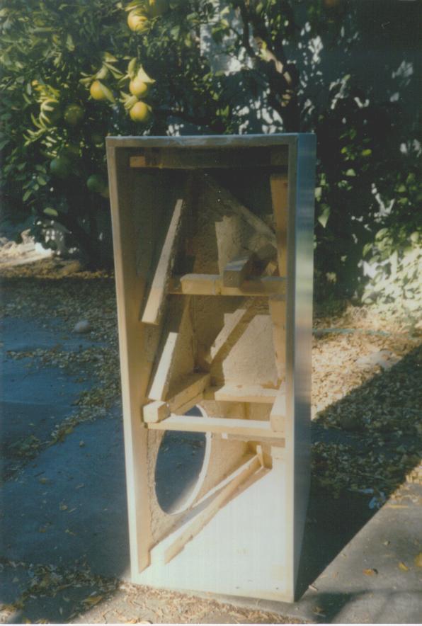 In this rear view, you can see
the L-shaped subwoofer chamber, the wall stiffeners, the 2-by-2 cleats
and braces, and the grey Shur-Stik coating.
In this rear view, you can see
the L-shaped subwoofer chamber, the wall stiffeners, the 2-by-2 cleats
and braces, and the grey Shur-Stik coating.
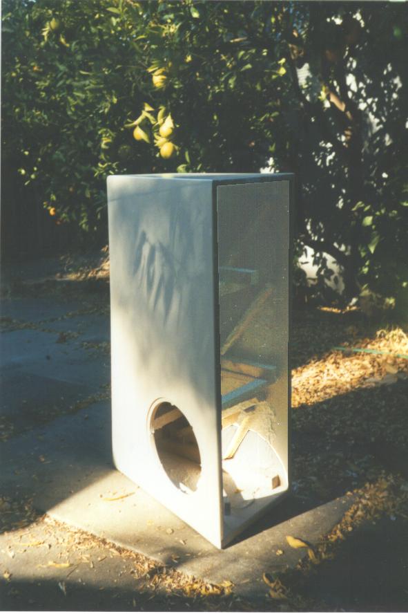 The same cabinet, viewed from a
slightly different angle, shows the “outer” side of the cabinet, the
mounting hole for the NHT 1259 subwoofer, and (through the hole) the
side-to-side brace which stiffens the subwoofer compartment. If the
inside of the cabinet looks a bit odd, it’s because I had to use The
GIMP to enhance the image - the original photo has such high contrast
that nothing was visible in the dark upper area.
The same cabinet, viewed from a
slightly different angle, shows the “outer” side of the cabinet, the
mounting hole for the NHT 1259 subwoofer, and (through the hole) the
side-to-side brace which stiffens the subwoofer compartment. If the
inside of the cabinet looks a bit odd, it’s because I had to use The
GIMP to enhance the image - the original photo has such high contrast
that nothing was visible in the dark upper area.
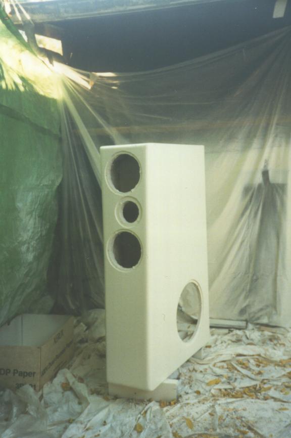 The same cabinet, viewed from the
front, after one of the “finish coats” has been applied. Note the
high-tech spray cabinet I constructed out of plastic dropcloths, string,
and duct tape. The little white rectangles positioned around the driver
mounting holes are bits of foam tape stuck over the Wel-Nuts to keep
them from being clogged by paint.
The same cabinet, viewed from the
front, after one of the “finish coats” has been applied. Note the
high-tech spray cabinet I constructed out of plastic dropcloths, string,
and duct tape. The little white rectangles positioned around the driver
mounting holes are bits of foam tape stuck over the Wel-Nuts to keep
them from being clogged by paint.
I used a combination of 3/4”-by-2” furring strips, and 1/4”-by-3” birch, to construct a large open-faced box on the back of each cabinet’s rear panel. I drilled holes in the rear panel, and installed brass bolts through the panel to act as feed-throughs for the subwoofer, mid/woofer, and tweeter connections. The crossover components (inductors and caps) were laid out in the open-faced box, glued into place using RTV silicone adhesive, and connected to one another and to the feed-throughs. I then soldered driver-interconnect wire to the feedthroughs.
The external crossover box serves several purposes. It puts the crossover out where I can get to the components, thus permitting me to “tweak” the circuitry if necessary. It keeps the crossover inductors well away from the driver voice coils and magnets, thus avoiding interactions. And, its walls stiffen the rear panel of the cabinet.
Finally, time to stuff the cabinets and install the drivers. I stuffed the upper portion of each subwoofer compartment (using about a pound of long-hair wool per cabinet) and fastened the rear panels into place (epoxy around the edges, epoxy on the ends of the cleats and braces, screws through the panels into the cleats and braces).
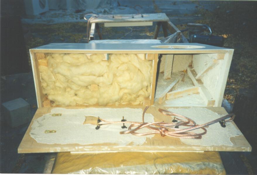 In this
picture, you can see the left cabinet just before the rear panel is
glued on... you can see the feedthroughs and the black silicone caulking
around their bases, the Shur-Stik glopping on the panel surface, and the
areas I marked out to avoid glopping in order to allow the epoxy a clean
surface to grab onto. Note the unglopped square near the upper standoff
- this “mates” with the end of the 2”-by-2” front-to-back brace you can
see sticking out of the wool stuffing. The silver nuts at the very top
of each rear panel are the mounting for a set of metal handles I
installed... these give me a secure handhold if I want to move the
cabinets around.
In this
picture, you can see the left cabinet just before the rear panel is
glued on... you can see the feedthroughs and the black silicone caulking
around their bases, the Shur-Stik glopping on the panel surface, and the
areas I marked out to avoid glopping in order to allow the epoxy a clean
surface to grab onto. Note the unglopped square near the upper standoff
- this “mates” with the end of the 2”-by-2” front-to-back brace you can
see sticking out of the wool stuffing. The silver nuts at the very top
of each rear panel are the mounting for a set of metal handles I
installed... these give me a secure handhold if I want to move the
cabinets around.
I ran the midrange and tweeter wires through a set of holes I’d drilled into the subcompartment, caulked the holes, and then stuffed the subcompartment and mounted the midwoofers and tweeters. Finally, I stuffed the bottom half of the subwoofer compartment and mounted the subwoofers. I ended up using a total of about 5 pounds of long-hair wool, and some acylic pillow-stuffing as well.
The drivers were all mounted using a tacky poster-mounting compound to form a sort of home-brew gasket, and screwed into the Wel-Nuts. The gasketing material isn’t entirely airtight, so I ran a bead of black RTV silicone around the outer edge of each driver, filling the gap between the driver and the routed-out recess.
I lugged the systems into the living room and set them up. These things are heavy! If I’d build them out of 1” MDF (or, even worse, double-thick 3/4” all around) they’d have been beyond my ability to handle by myself.
As I had not yet assembled my Marchand XM9 crossover, I hooked up the MTM array alone. My first impression was that the systems were a bit bright, and bass-shy. After a few weeks of breakin, the bass opened up a bit, but was still low in impact. This didn’t surprise me, as I’d known the 18W8545s would roll off at a relatively high frequency when used in a sealed enclosure.
Over the weeks that followed, I assembled the Marchand crossover, dug out my spare amplifier, and switched over to a biamplified arrangment. Much better! The bass is now clean, solid, and honest - no boominess at all. It sounds extremely natural - string bass, drums, etc. sound neither anemic nor exaggerated. Driver-to-driver integration is extremely good.
Some of the excessive brightness remained after breakin. This didn’t surprise me too much - Brian had warned me that I might want to increase the value of the tweeter “padding” resistor a bit. Before I did that, though, I built a set of grill covers for the cabinets (using a stiff sheet of plastic foam for the frames, and an acrylic fabric for the covers). The grill cloth tamed the brightness in the treble... in fact, it dulled the treble too much. I installed a set of shorting jumpers across the tweeter padding resistors in the crossover, and the sound achieved a very pleasant balance.
I committed fully to the new speaker system this weekend. I sold my venerable Fried B/2 / T setup to another net.audiophile. Fortunately, he had strong arms and a large vehicle...
I built a new set of grill covers, replacing the old ones. The original grill-cover design suffered from a couple of problems. The acrylic fabric I used had a fairly close weave - it was not acoustically transparent. The frames, constructed of 1/4” plastic foam, were not very rigid - I couldn’t stretch the fabric taut without distorting the frames, and as a result the fabric was becoming rather “droopy” and actually touched the lower woofer surrounds. And, finally, the covers were fastened to the baffle using wads of poster-tak, which wasn’t holding all that well - they kept coming off.
The new grill-covers are of a more conventional design. I made frames out of 1/2”-radius pine quarter-round, mitered at a 45-degree angle at the ends and glued with epoxy. Inside each corner, I glued a triangular piece of 1/2” pine, to serve as a strengthener for the corners and as a place to put a ball-and-socket fastener. The balls went into holes in these braces (press-fit, reinforced with epoxy), the sockets went into corresponding holes drilled in the front baffle (press-fit, no epoxy needed), and the frames were given a quick spray-coat of white paint. I cut pieces of white grill-cloth fabric (ordered from Parts Express, along with the fasteners), ironed, tensioned, and stapled. Voila! Much less trouble than I thought they’d be.
The new grill covers are much more sonically transparent than the old ones - I’ve removed the shorting clips around the tweeter padding resistors. They’re visually semi-transparent, too - one can see the drivers behind them to some extent.
I’ve soldered up a bunch of resistor modules for the Marchand XM9 active crossover. The original module supplied by Marchand sets the crossover frequency to 100 Hz. I’ve made modules for 140 Hz, 200 Hz, and 275 Hz, and have started some listening tests to see which crossover frequency sounds best in my system.
My hope is to find a crossover setting which largely avoids the “floor reflection” cancellation effect, which tends to cause an audible dip in the midbass. The original 100 Hz crossover is vulnerable to this suckout, since the midbass frequencies are being routed to the MTM array several feet above the floor. By pushing the crossover point to a higher frequency, the midbass would be routed to the side-mounted NHT 1259 woofers - these are close enough to the floor that the floor-reflection cancellation would fall above the crossover frequency and would have little or no audible effect. As an additional benefit, this change may also reduce distortion in the 18W8545s, as they’ll be handling a smaller range of frequencies, with less power and less cone excursion.
The first new module I tried out was 275 Hz (it was the only one for which I had suitable resistors in my supply box). I wasn’t too happy with the result. The midbass frequencies were fuller, but sounded somewhat wooly and loose - they didn’t integrate as well with the upper bass and midrange. I’m not too surprised at this - asking the side-mounted 12” 1259 drivers to handle frequencies this high probably isn’t a terribly good idea.
I stopped by the Friendly Neighborhood Electronics Surplus Store and bought resistors for the 140 Hz and 200 Hz modules. I’ve installed the 200 Hz modules now, and am a good deal happier with the results. The midbass sounds fuller and more realistic than with the 100 Hz modules, but doesn’t suffer from the looseness and poor integration I heard with the 275 Hz modules.
I’ll listen to the system this way for a week or two, and then try out the 140 Hz modules. I might make up some more modules for intermediate frequencies... but I’ll have to wait until the store renews their stock of 8-pin DIP component carriers, as I’d bought out their supply.
I’ve been using the 200 Hz crossover modules for the last six months. In my system, this seems to be the best crossover frequency - it works better than either 100, 140, or 275 Hz.
I did some tuning to the passive (MTM) crossover yesterday. When Brian Smith adapted his Signature 7 crossover for my cabinet, he deliberately set the value of the low-pass inductor to be a bit on the small side, in an attempt to give the 18W8545 carbon-fiber drivers something of the additional “liveness” of the 18W8546 Kevlar drivers he was used to working with. He warned me that this might possibly result in a bit too forward a midrange.
After listening to the system on a wide range of program material for an extended period, I decided to try his alternative suggestion: increasing the value of the lowpass inductor from .87 mH to 1 mH. This causes the midwoofers to begin rolling off a bit sooner, reducing the system’s output in the midrange region.
I also did the final set of cosmetic work on the cabinets - I fabricated a set of grill covers for the side-mounted NHT 1259s and mounted them into place. The construction was quite similar to the method I’d used for the front covers - 3/4” pine quarter-round, sawn at 45 degrees in a miter box, epoxied to form a square frame (18” on a side), equipped with ball-and-socket mounts, spray-painted white, covered with white grill cloth. At this point, the system no longer has any “bare” drivers - all four drivers per side are dimly visible through the grill cloth but are not visually intrusive.
1/8/98 - Stability at last?
After having listened to the system with its modified passive crossover for five weeks, I’m quite happy with the result. The system’s excessive forwardness has been tamed - the system sounds neither forward nor recessed, and the midrange now has a better balance with the bass. I’m now a very happy camper.
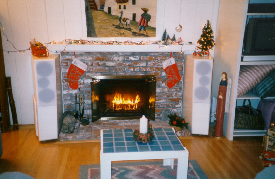 Here’s a photo of the systems in our living room, during the 1997/1998
Christmas holiday season. This shows both cabinets in place on either
side of our fireplace, with all of the new grill covers in place.
Here’s a photo of the systems in our living room, during the 1997/1998
Christmas holiday season. This shows both cabinets in place on either
side of our fireplace, with all of the new grill covers in place.
You can see that my wife’s fond of having twinkling Christmas lights, and plenty of Christmas decorations! She’d probably have been happier if the speakers were physically smaller... but she’s content with them, as they’re a lot less obvious than the old ones.
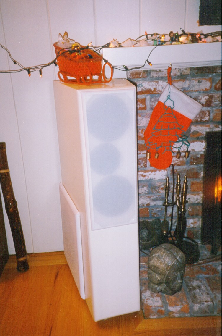 This is a
closer view at the left-hand cabinet, in its location by the
fireplace.
This is a
closer view at the left-hand cabinet, in its location by the
fireplace.
After about a year of listening, I can say that I’m quite happy with the sound I’m getting. The new system is definitely cleaner, more detailed, and more natural than the Fried system it replaced. On bad recordings, it can be rather unforgiving at times. On really good recordings, it’s lovely. Some of the woodwind passages on In The Labyrinth’s CD “Garden of Mysteries” make me fall back on the couch, close my eyes, grin, and murmer “Oh, yes! This is why I did all that work!”
My total investment in this project was somewhere on the rough order of $2000... including tools like the router, circular saw, and paint sprayer that I’ll certainly be continuing to use for other purposes, but not including the assumed value of my time (many, many hours!). It was a valuable learning experience and a lot of fun. I think I ended up with a better set of speakers for the dollar - and a much better match for what my wife and I wanted - than I could have gotten on the commercial market.
This was an extremely aggressive and challenging speaker design for me, as it was my first “from scratch” design. A lot of things could have gone wrong. Fortunately, very few did.
I’m very grateful to Brian Smith of Just Speakers for his willingness to share the Signature 717 crossover design with me - he’s clearly done a lot of work to optimize this design, and it certainly works better than any sort of “cookbook” design I could have done on my own.
If you’re interested in my plans and circuit schematics, you can go here for further information.
Feel free to send me email if you have comments or questions concerning this project.
Go here to reach my home page.
Go here to reach the Jade Warrior home page.